Mesh Proxy_Color Mode
发布于:2024-11-21
Feature Overview
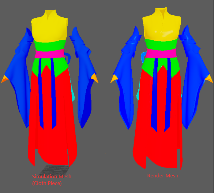
In DCC (Digital Content Creation), different vertex colors are painted for different areas of high-resolution render meshes and low-resolution simulation meshes.
Proxy relationships are manually created in UE (Unreal Engine) based on vertex colors.
supporting vertex-level proxy creation.
Steps
1. Color Separation in DCC
Split mesh vertices by proxy relationship, setting different vertex colors for different regions.
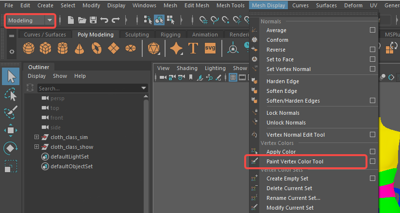
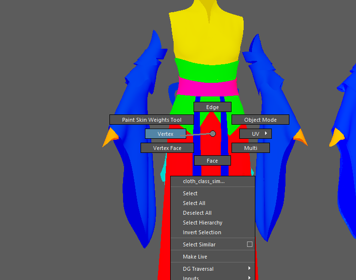
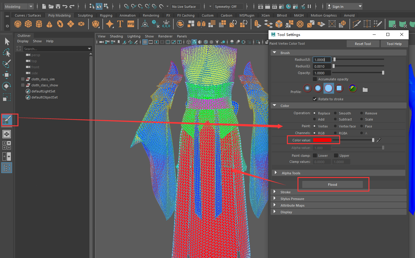
Method 1: Paint model vertex colors.
Method 2: Use color ID maps.
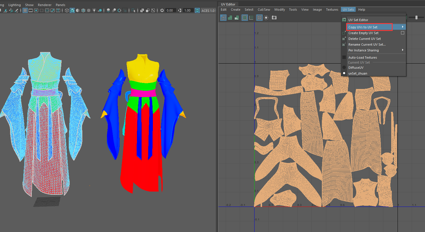
For high-resolution render meshes, add a UV set and arrange UVs in the first quadrant. Set different groups and add different color materials.
In face mode, select mesh faces and assign new materials (regular Lambert works).
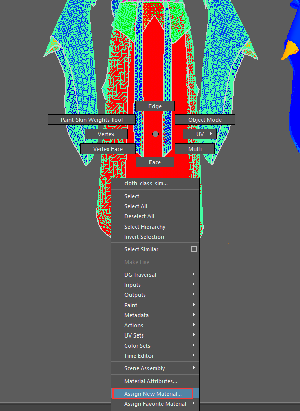
Assign different colored materials to all meshes.

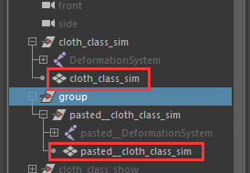
Copy the mesh.
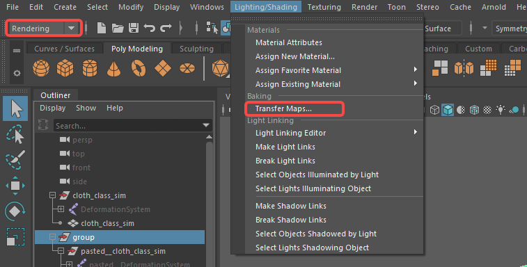
Select Bake -> Transfer Maps to bake and export UV maps with colors.
Target Mesh: Copied mesh.
Source Mesh: Mesh with grouped materials.
Diffuse Color Map: Storage path and file name.
Transfer: Select UV space.
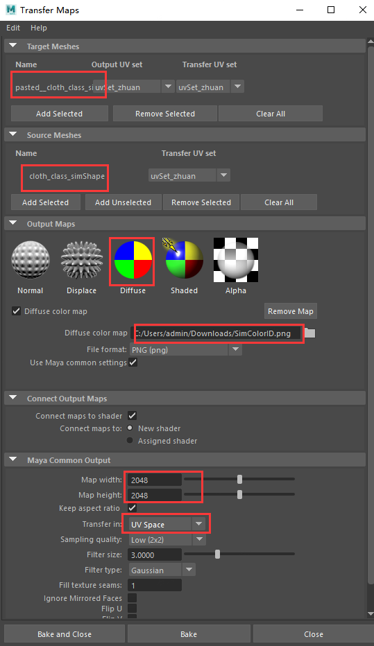
Find the baked ID map in the directory.

Use the above method to get the ID map for the simulation mesh (no need for a new UV set for the simulation mesh, UV0 channel can be used).
2. Setting Up Proxy in UE
Create the simulation mesh as a clothing asset using the generic mesh simulation function to create it as a Style3D clothing asset from the FBX.
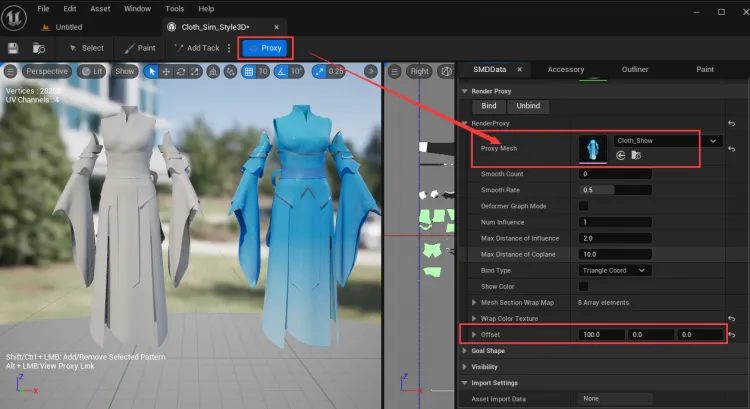
Proxy Mode:
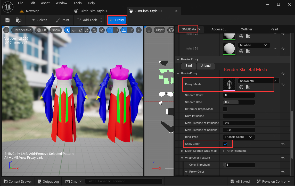
Click Proxy Mesh Proxy Mode, add a render mesh skeletal mesh component, and set the Offset.
Show Mesh Colors: Check Show Color to display vertex colors in the 3D window.
Load Color Map (Optional):
If no color map is configured, the model's vertex color is displayed. If a color map is configured, the color of the map is displayed.
Wrap Color Texture: Enter the color map in the respective fields.
Proxy Color: Render mesh color map.
Piece Color: Simulation mesh color map.
UV Channel: UV channel to apply the map.

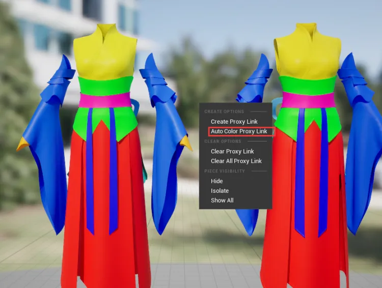
Creating Proxies:
Clear all proxies by right-clicking before creating new ones.
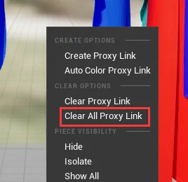
Method 1: Automatically create proxies for areas with the same color by right-clicking and selecting Auto Color Proxy Link.
Method 2: Manually create proxies by selecting the mesh of the simulation and render meshes and right-clicking to Create Proxy Link.
Mesh Selection Notes:
Single-clicking the simulation mesh selects the piece, single-clicking the render mesh selects the section.
Double-clicking either mesh selects the topologically connected same-color area.
Shift/Ctrl + single-click adds/removes pieces in the simulation mesh or sections in the render mesh.
Shift/Ctrl + double-click adds/removes color areas.

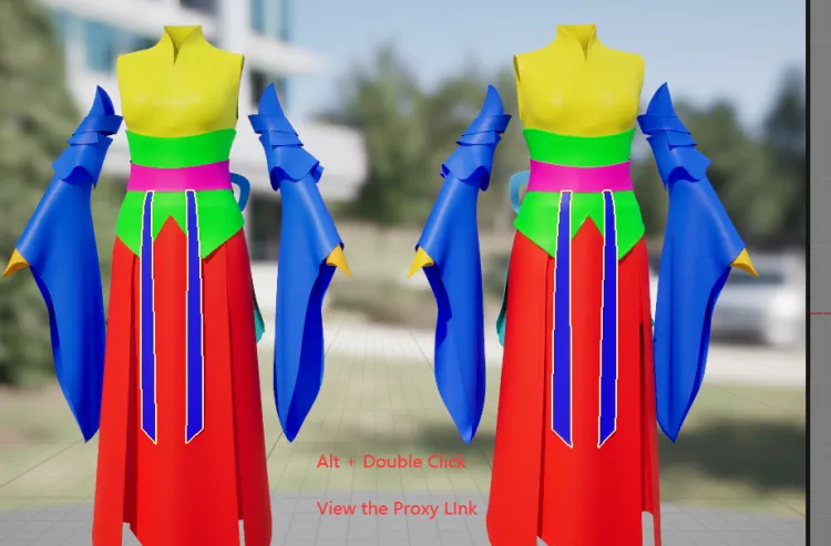
View Proxy Relationships: Hold Alt and double-click the color area of the render mesh to simultaneously display the simulation mesh with proxy relationships.
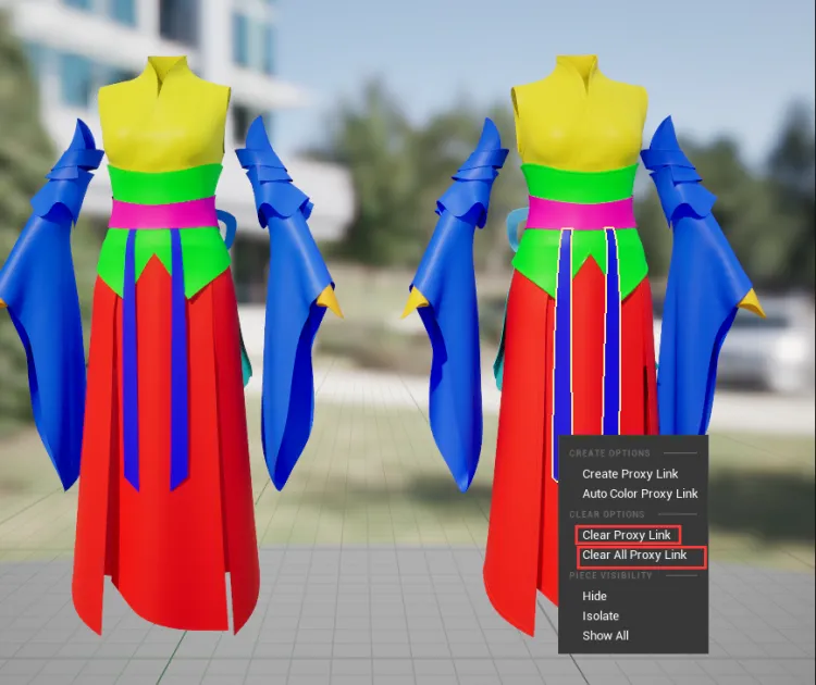
Clear Proxy Relationships:
Select a color area, right-click, and choose Clear Proxy Link to clear the current proxy relationship.
Right-click and select Clear All Proxy Link to clear all grouped proxy relationships.
Save and Apply Proxies: Click Bind to apply all created and modified proxy relationships. Reset render mesh offset and hide the simulation mesh.


Common Issues
When both index proxy relationships and color grouping proxy relationships exist for a piece, the color mode proxy (higher priority) is used. If no color mode proxy exists, the index mode proxy data is used.